Maze Solving Robot
This is a video of my Maze Solving Robot in an early navigation stage.
In this final lab for Intelligent Physical Systems [ECE 3400], our goal was to assemble all the parts of our previous labs into one script. This includes the phototransistors for LED detection, microphone and op amp circuit for frequency analysis, antenna for receiving and sending radio information, ultrasonic sensors for wall detection, and servos for movement.
Adding an RF transceiver
The newest component of our robot is the RF transceivers we used in this lab. These were easy to assemble and attach as they only used a few pins. We adapted code to use our specific send channel and tested the transceivers with dummy variables. These numbers would eventually have to be combined with the display code for the base station we built earlier in the course. We also figured out how much power we needed to use to ensure that the radio information package would be received by the base station and displayed at a certain distance. This concluded the additions we had to make to the robot to be ready for the final demo.
Finalizing the robot and code
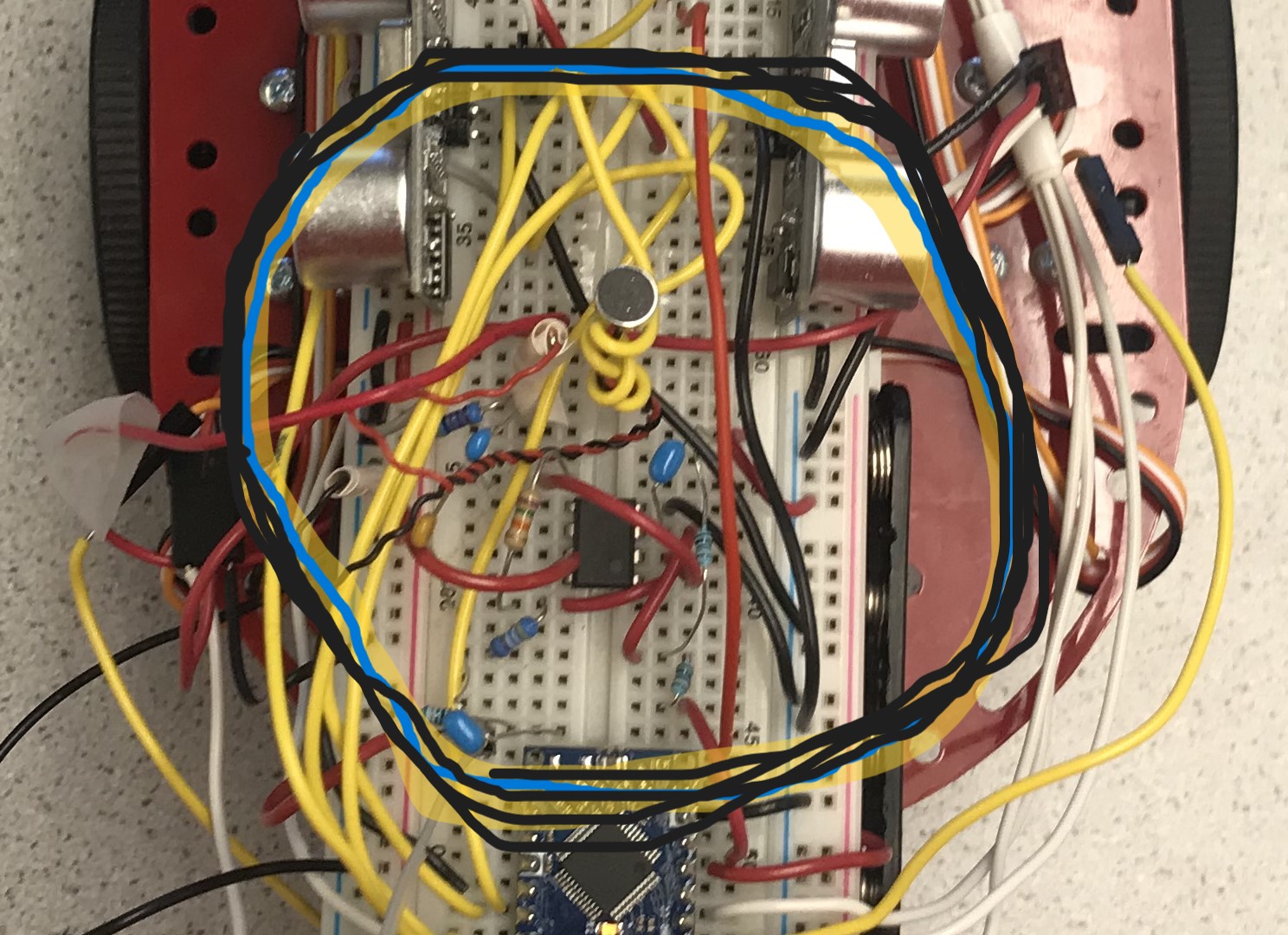
The robot had to be triggered to start by a 440 Hz frequency. This is why we implemented the microphone circuit in lab 3. This circuit is outlined in the picture below. It also includes an override button (not pictured) in case the FFT fails to recognize the proper frequency.
The robot’s final task was to be able to navigate through a 5x5 block maze. To ensure that the robot navigated to all possible locations inside the maze, we implemented a depth-first search algorithm. Additionally, we had a protocol for dicretizing the maze structure into 25 coordinates, which required precise PID control and turns. In our final version of the navigation code, we implemented a pretty barebones PID which only took the P (Position) term into account, and also swerved extra hard if it was particularly close to a wall.
This PID control had issues; for example, the robot performs best when it moves orthogonally, as the maze itself is full of 90-degree turns. If the PID shifted the robot off of its starting orthogonal alignment, the rest of the navigation would have trouble figuring out exactly where it was or what it was doing. To improve our design, I implemented feedback-enabled turns, which were supposed to make the turns a lot more precise, but the feedback results were spotty enough that these turns were not any better than the delay-based turns we had implemented in lab 1, which was dissapointing.
Additionally, there were many cases within the maze where the robot would not be able to perform PID using both the left and right sensors. In these cases, we made specialized functions that would only refer to the PID input on the closest wall. Below is a picture of the final maze our robot navigated.
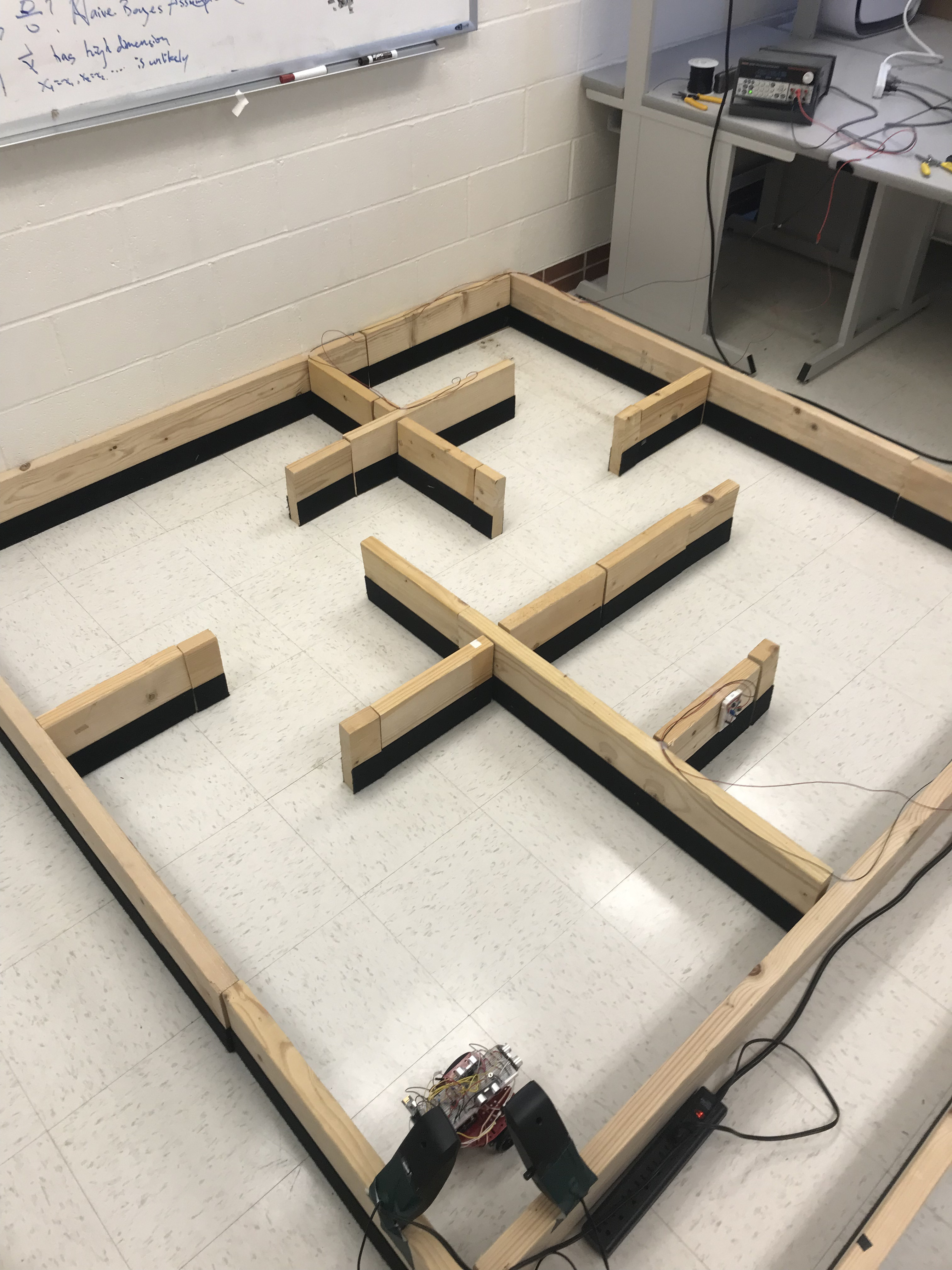
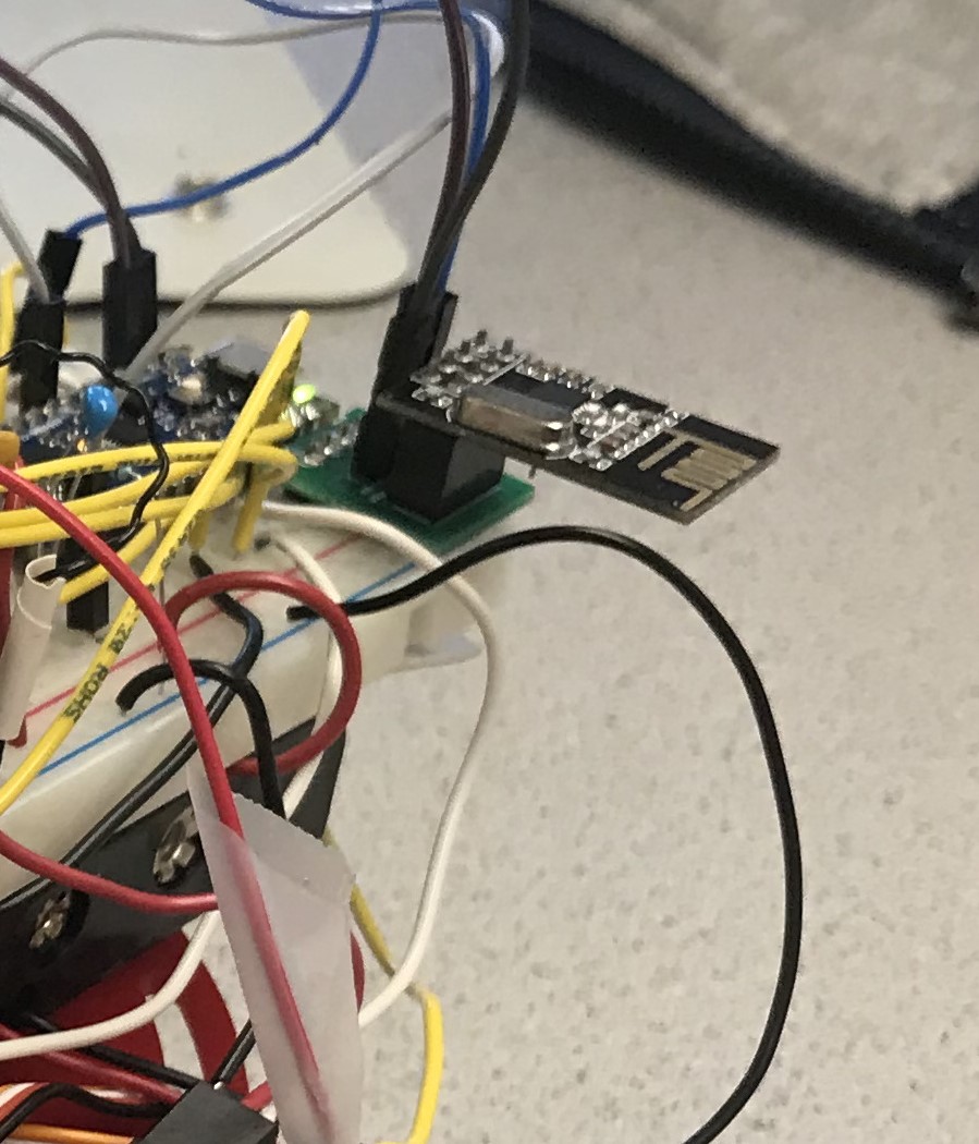
Another component of the maze search was to find the two IR LED “treasures” pictured in the maze above (such as the device attached to a red wire on the right). To do this, we adapted our phototransistor code from lab 2. Additionally, we ensured that if the robot were to encounter a treasure while searching the maze, it would stop searching for a minute and transmit the frequency of said treasure out to the bay station via the RF antenna. Below is the antenna:
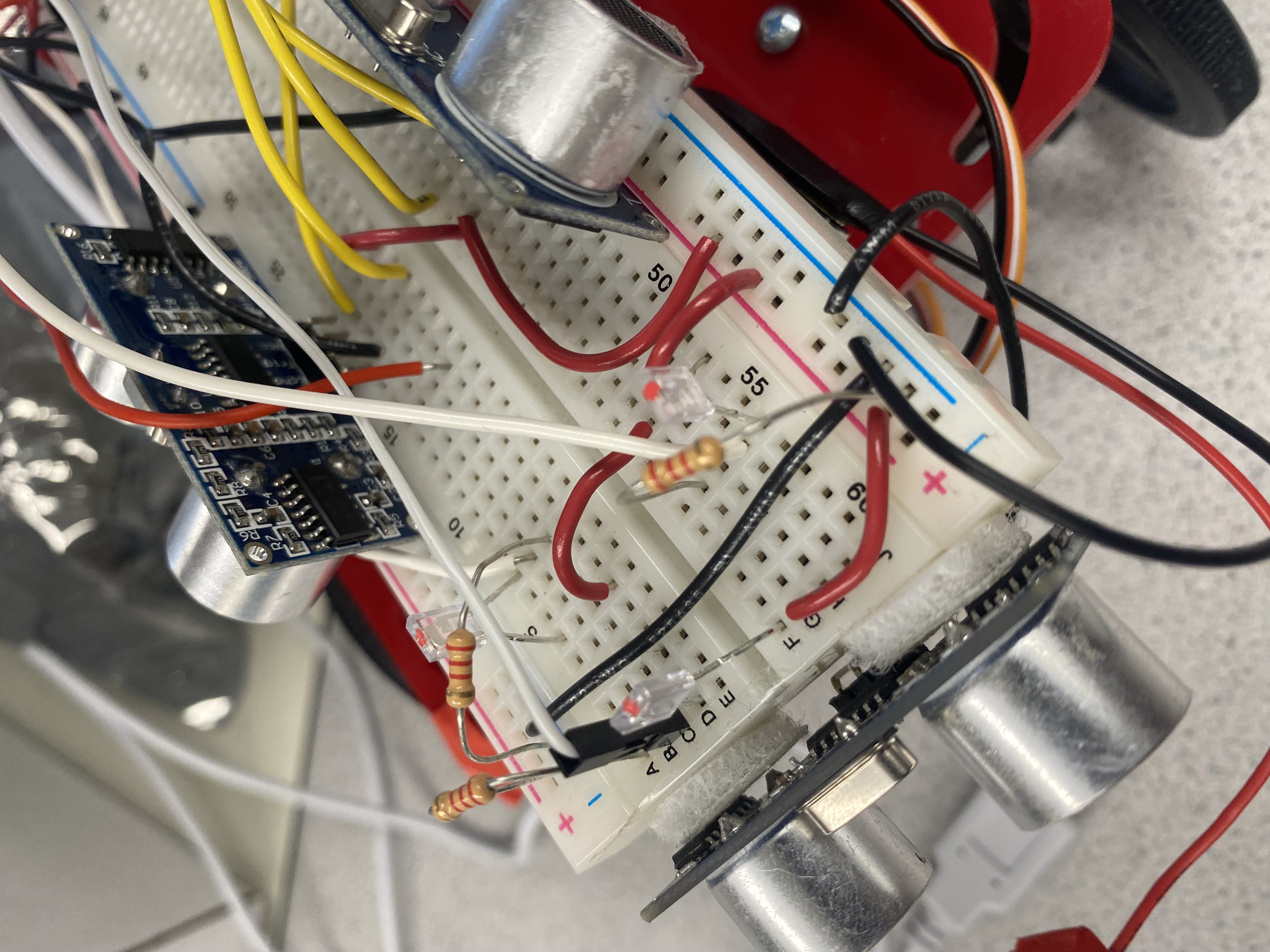
A picture of the robot’s phototransistors:
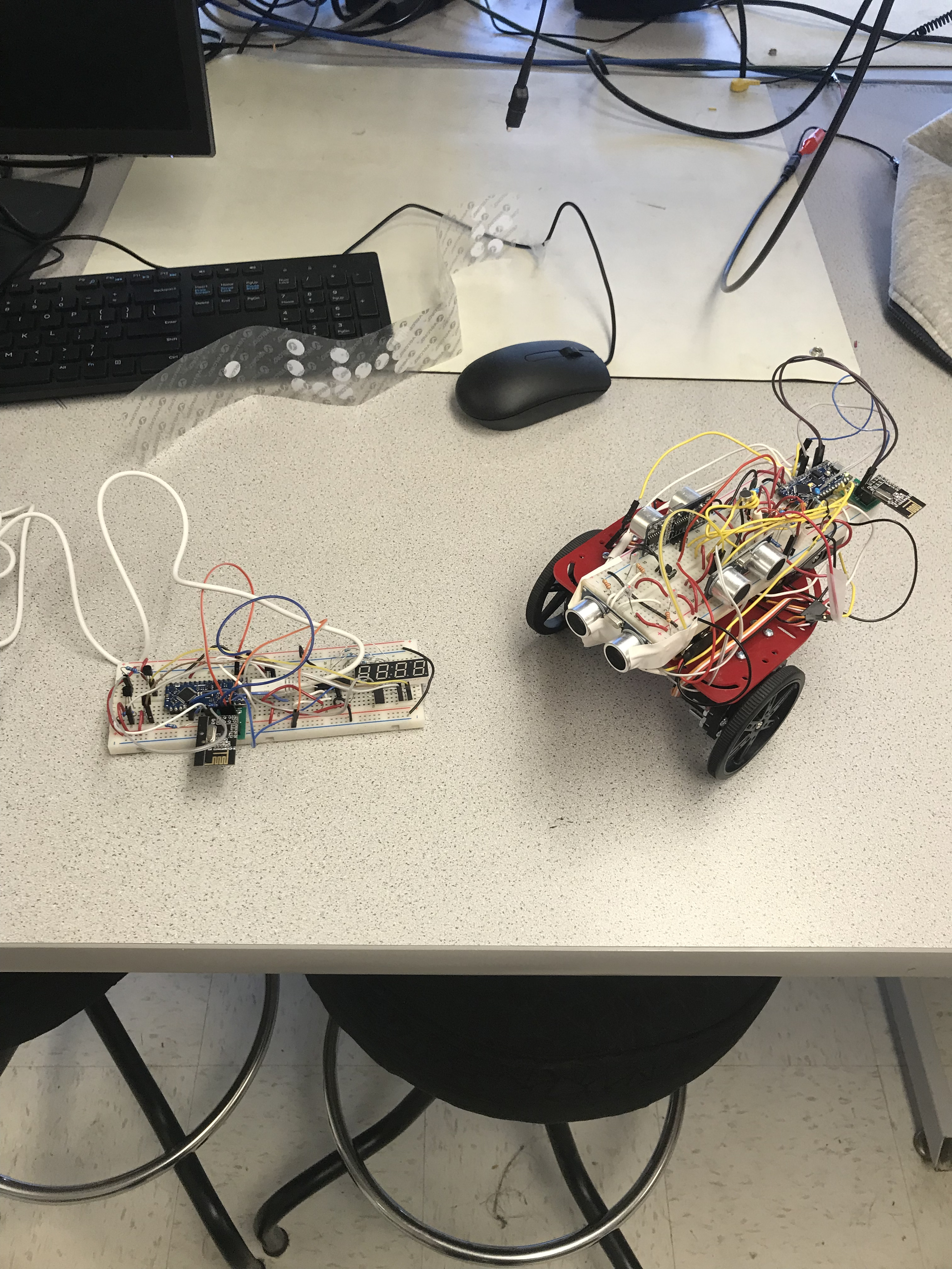
A picture of the robot and bay station together:
Concluding thoughts
I’m fairly happy with the final result of our robot. One of the hardest parts of this project was making sure each and every disparate element worked properly in the main code we ran on demo day. We experienced multiple issues with either the phototransistors or the radio transceiver not working properly, which we were able to temporarily resolve by replacing the hardware in each such case. Dissapointingly, during the final demo, our robot did not properly report the treasure LED’s frequencies, which I will ascribe to a hardware malfuntion as we had the process working properly the day before.
Another difficulty we faced in the project was the PID and movement. Given the limited time I had to work on this issue, I feel as if I gave it my best effort, but I would have liked to make a more foolproof protocol for the robot’s motion that was not reliant on the error-prone, delay based turn function. The PID itself could also definitely have been improved if I had successfully been able to implement the D (Derivative) functionality. However, the edge cases we created worked as intended and our reasoning regarding movement was sound, so I’m satisfied with the end result we created. The culmination of this project was a great way to end ECE 3400, and I’m thankful to the course staff and my lab partner Charlie for working with me throughout the class.